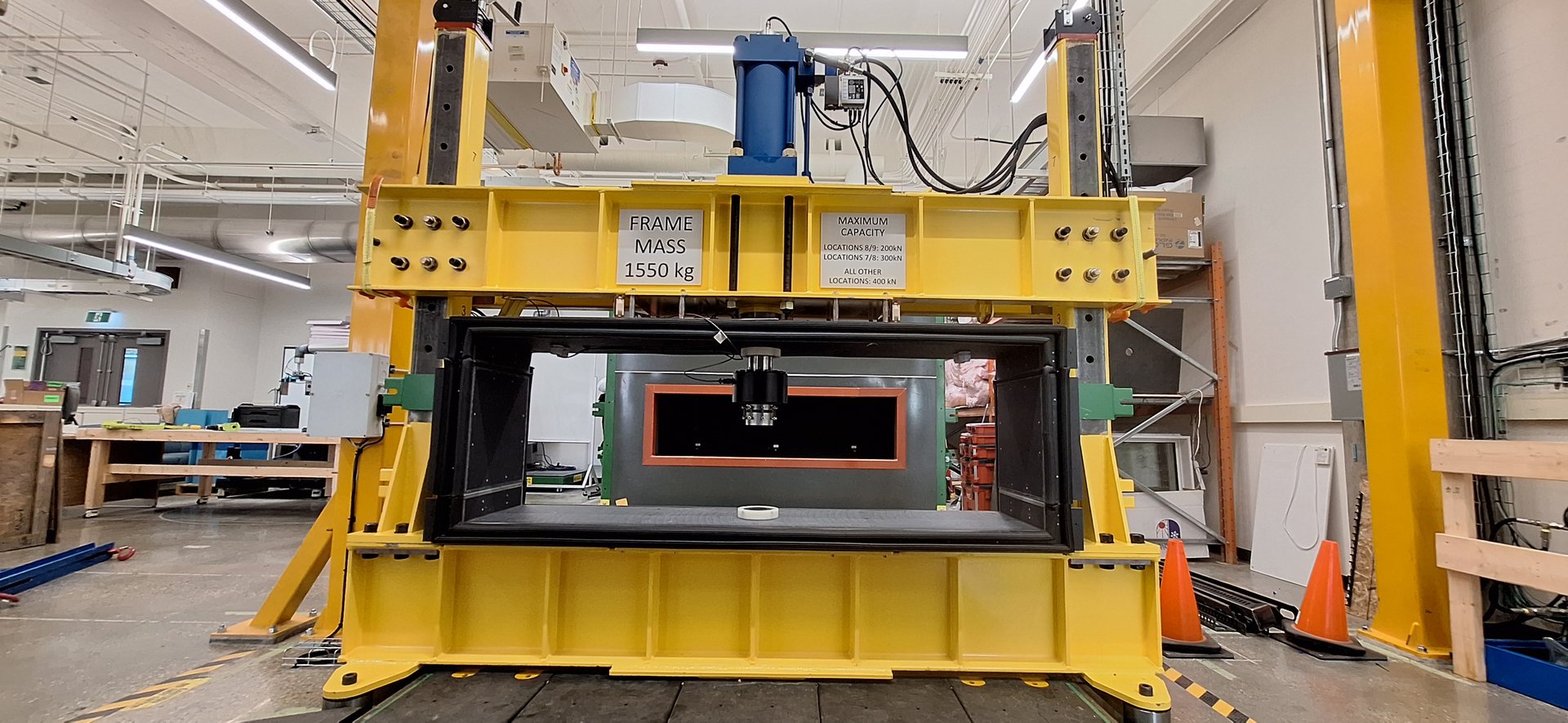
Structural frame
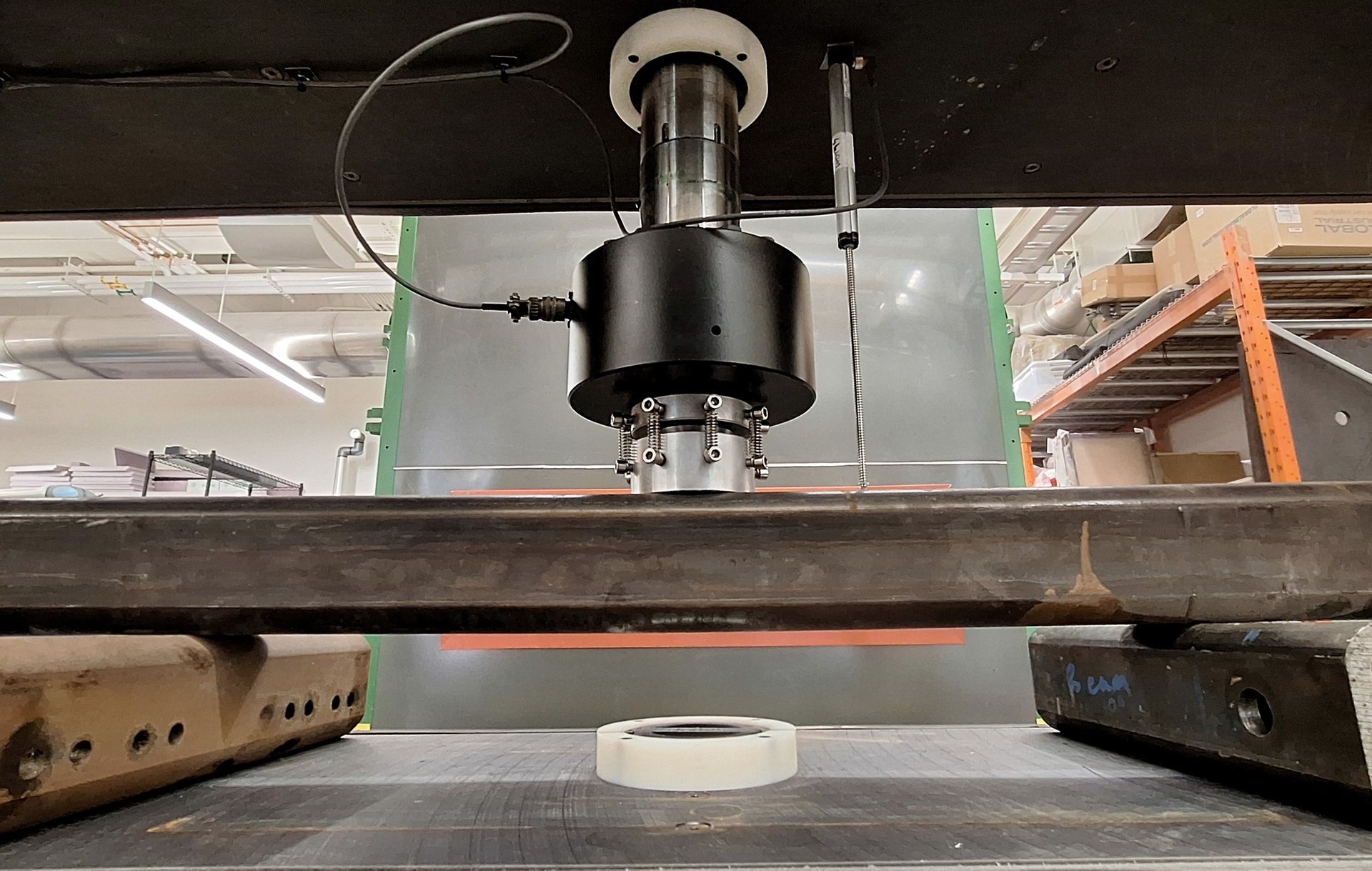
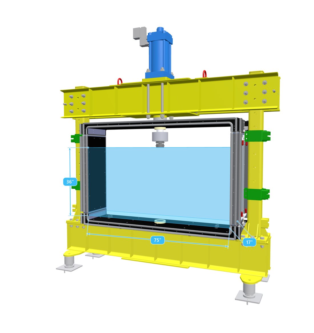
A hydraulic cylinder loads the specimen in compression, tension or a programmed cyclic routine, while the sealed enclosure holds the climate around it, steady or driven through a profile.
Structural testingStructural and Thermal Evaluation in Extreme Environment
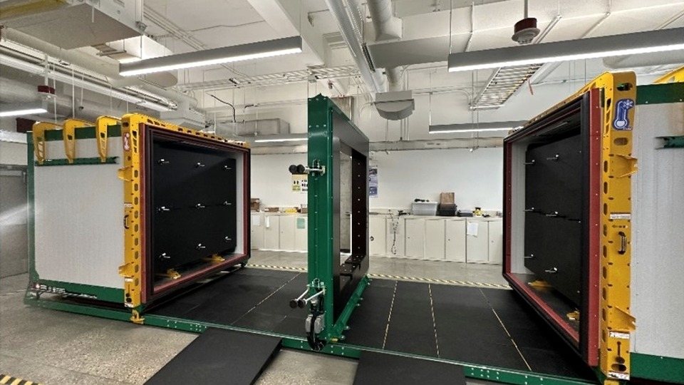
A full-scale environmental chamber at the University of Alberta. Two climate chambers on a shared rail system, and a test bay between them that accepts either a structural load frame or a thermal test frame, so a real assembly can be loaded, or metered for heat loss, in the climate it will actually have to survive.
Every building lives or dies at its envelope. Heat, moisture and structure all converge on the building’s skin, and catalogue numbers and models routinely miss what real assemblies do once thermal bridges, air gaps, fasteners and workmanship are in the picture.
The only way to know is to test the real thing, at full scale, in real conditions. STEEE is the platform for it: a hot chamber and a cold chamber running independent climates on either side of a central test bay. The shells are R-32 insulated, and the whole machine runs from a single PLC and touchscreen in the control cabinet.
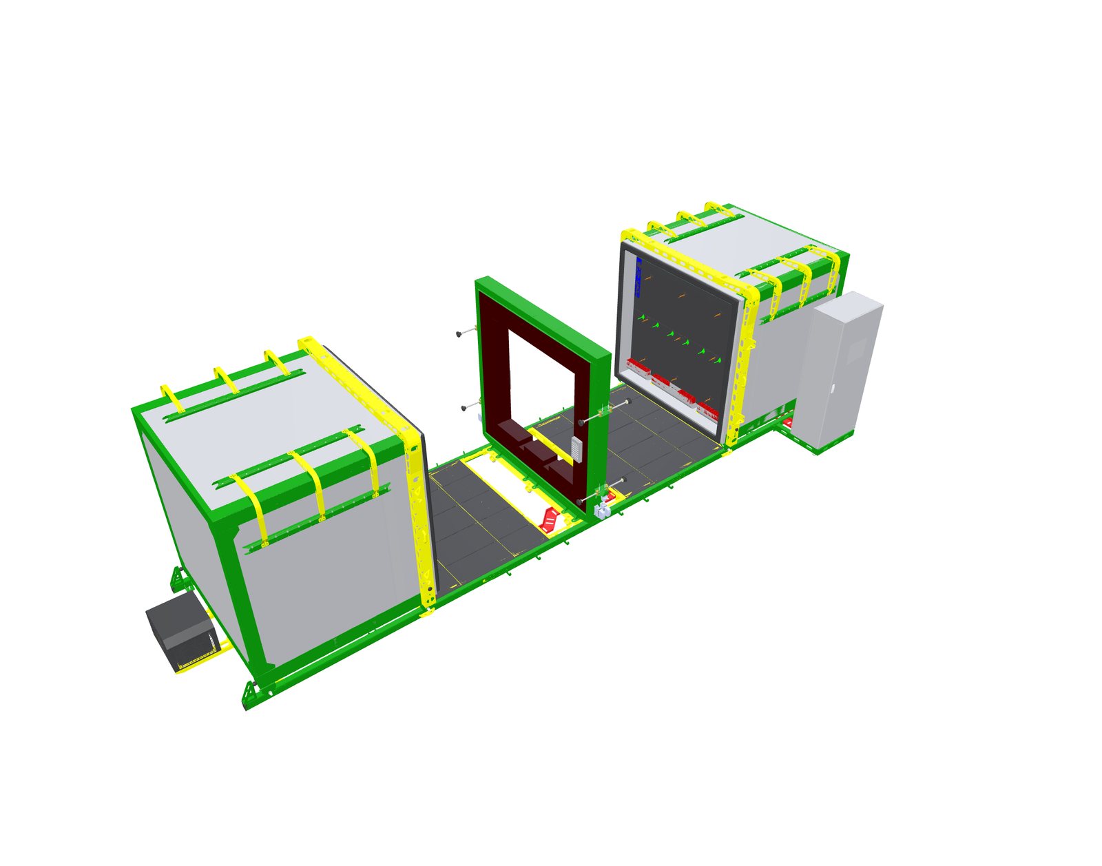
The central bay accepts either of two interchangeable frames. One is installed at a time and the other is stored in the lab; swapping them is a crane lift.
A hydraulic cylinder loads the specimen in compression, tension or a programmed cyclic routine, while the sealed enclosure holds the climate around it, steady or driven through a profile.
Structural testing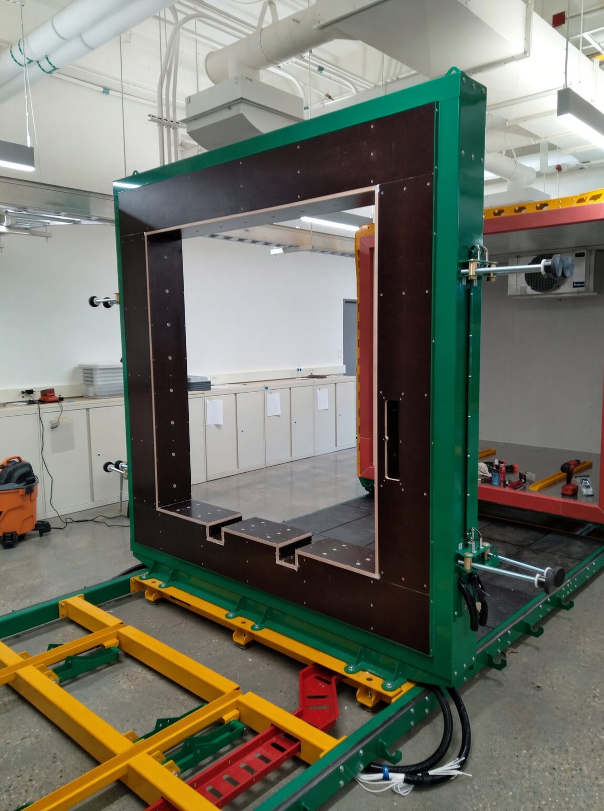
The specimen becomes the wall between the two chambers. One side runs indoor conditions and the other runs outdoor conditions, and the heat flow through the assembly is determined from the energy needed to hold those conditions steady.
Thermal testingMechanical loading inside a controlled climate: compression, tension and programmed cyclic loading, with the chamber holding temperature and humidity throughout.
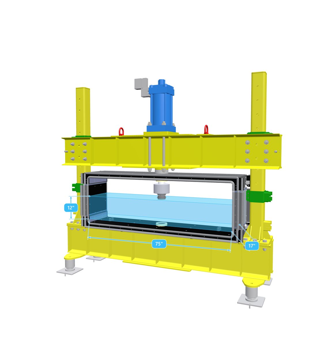
With the thermal frame in the bay the specimen becomes the wall between the chambers, and heat flow through it is determined by the ASTM C1363 calibrated hot box method, which is what building codes reference. The chambers are held at steady conditions and the energy required to maintain them is measured, so the result describes the assembly as it was built rather than the value calculated from its materials.
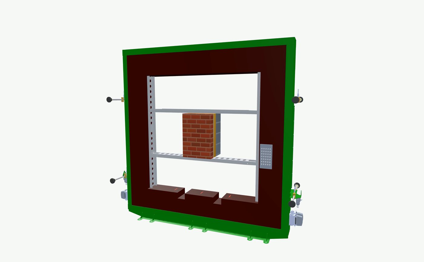
Class A RTDs at ±0.15 °C, with 72 ports on the specimen frame alone, logged continuously alongside airflow, humidity and heater power.
The servo valve runs on LVDT feedback or on pressure feedback. That choice is what puts slow monotonic ramps and long cyclic programs on the same rig.
A rod-position LVDT gives piston displacement; additional LVDTs can pick up deflection at several points along the specimen, and strain gauges can be added.
Chamber setpoints follow a profile as readily as they hold a steady state, so freeze–thaw cycles and diurnal swings run unattended.
The chamber is available for collaborative research and for contract testing. If you have a wall, roof, connection or component whose performance you need measured, tell us what you are trying to determine and we can advise on whether a test here would answer it.